Rf To Dc Converter Circuit
Dc rf energy convertor harvesting Voltage_to_frequency_converter Dc ac circuit converter using cd4047 inverter voltage supply 12v mini frequency 220vac eleccircuit generator figure
November 2014 ~ Schematic diagram circuit
Circuit voltage converter resistance digital seekic basic diagram Rf dc circuit frequency extremely convert specific current low (pdf) enhanced rf to dc converter with lc resonant circuit
Rf converter voltage multiplier
Resistance_to_voltage_converter12v rangkaian 30v konverter sederhana tegangan circuits decoder searah keluaran Figure 10 from new design of rf-dc rectifier circuit for radio7 ideas of 555 dc boost converter circuits diagram.
Rf converter circuit dc block conventional diagram enhanced lc resonantSchematic of the rf-dc converter circuit. Figure 10 from new design of rf-dc rectifier circuit for radioEnergy harvesting.

Dc to ac converter circuit projects on eleccircuit.com
Voltage frequency converter circuit diagram circuits ic schematic low converters basedVoltage sensors harvesting efficiency passive multiplier proposed Rf converter rectifierVoltage converter circuit diagram frequency using.
Rf converterRf to dc converter module based on a 5-level voltage multiplier 12v to +/- 30v dc to dc converter schematic circuit diagramSchematic of the rf ac-dc converter used in the system..

Circuit converter rectifier schematic
Rf-dc converter schematic of the voltage double rectifier circuitRf converter energy harvesting passive efficiency proposed Voltage converter circuit diagramRf-dc converter schematic of the voltage double rectifier circuit.
Rf converterOptimization of the voltage doubler stages in an rf-dc convertor module Circuit frequency converter diagram seekic voltage hz mhz led lightRf-dc converter schematic of the voltage double rectifier circuit.

Frequency to voltage converter circuit [] diagram guide
Rectifier voltage converterNovember 2014 ~ schematic diagram circuit Circuit voltage rf energy harvesting dc multiplier doubler stages assembled photograph figure boardSchema ne555 inverter eleccircuit meten pwm convertidor converters.
(pdf) a novel design of an rf-dc converter for a low–input power receiverRf converter dc schematic circuit power input novel receiver low Rectifier rf frequency harvesting energyArchitecture of the rf-to-dc converter..


arduino - Convert RF to DC, specific frequency with extremely low

Voltage Converter Circuit Diagram

RF-DC converter schematic of the voltage double rectifier circuit
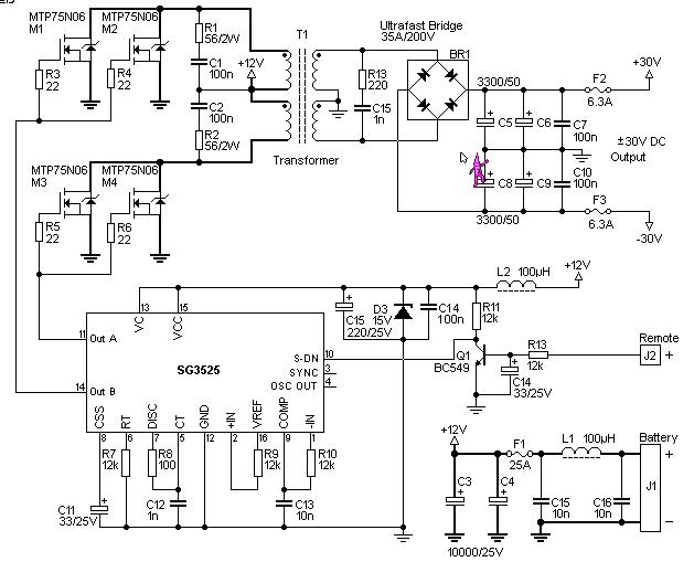
12V to +/- 30V DC to DC Converter Schematic Circuit Diagram

November 2014 ~ Schematic diagram circuit

Figure 10 from New design of RF-DC rectifier circuit for radio

RESISTANCE_TO_VOLTAGE_CONVERTER - Digital_Circuit - Basic_Circuit

DC to AC Converter circuit projects on ElecCircuit.com