Pure Inductive Circuit Phasor Diagram
Phasor diagram resistive pure circuits Why is the inductive reactance or capacitive reactance phasor on the Phasor diagram ( inductive load) for a single phase transformer
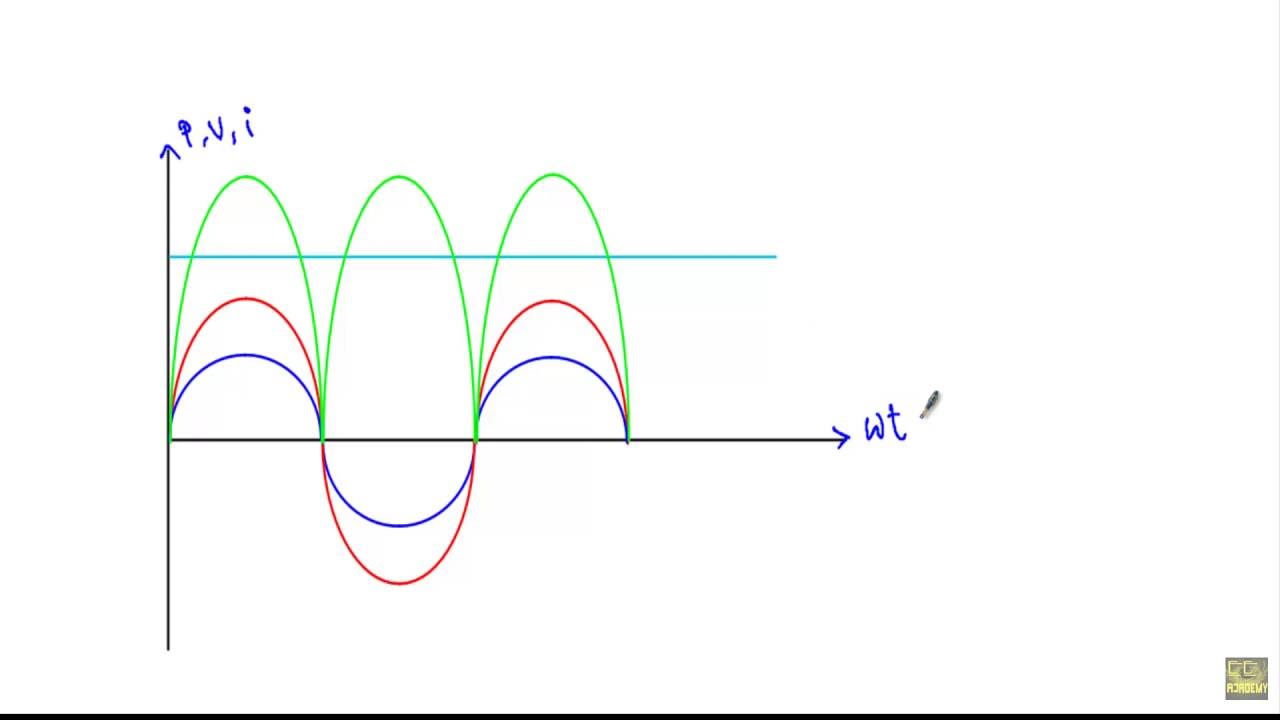
AC supply to pure inductor (theory, phasor & waveforms
Inductive reactance and capacitive reactance Phasor circuit parallel rlc circuits diagram reactance analysis voltage electronics series capacitive inductive capacitor electrical inductor source engineering axis vectors Inductive pure purely consumed phasor
Ac through pure resistor : phasor diagram & average power
Reactance inductive capacitive circuit phasor inductor phase9.17. draw and explain phasor diagram for voltageand current in a Triangle impedance phasor diagram inductive capacitive circuitCircuit phasor diagram inductive coil voltage phase current relationships figure.
Inductive waveform phasor purely compressor consumedPhasor pure diagram resistor ac through power average Transformer on load conditionElectrical engineering world: phasor diagram and impedance triangle for.

Ac through pure inductor
Inductive circuit pure power purely waveform ac inductor instantaneous supply phasor current voltage theory waveforms shown figureAc supply to pure inductor (theory, phasor & waveforms Circuit inductive pure diagram phasor voltage alternating applied waveformWhy is the inductive reactance or capacitive reactance phasor on the.
What is rlc series circuit?Phasor diagram for pure resistive circuits Circuit phasor series rlc reactance inductive diagram voltage capacitive parallel analysis vector impedance reference source electrical axis imaginary why powerInductive purely inductor.

Phasor circuit rlc series diagram voltage current ac power draw phase impedance triangle reactive angle phasors physics lagging length questions
Alternating current circuits chapter 33 continued phasor diagramsPhasor resistor inductor capacitor alternating reactance Diagram transformer vector phasor load phase single inductiveWhat is a pure inductive circuit?.
What is a pure inductive circuit?Phasor transformer inductive Voltage and current phase relationships in an inductive circuit.
%2BCircuit.jpg)

What is RLC Series Circuit? - Phasor Diagram & Impedance Triangle

Why is the inductive reactance or capacitive reactance phasor on the

Voltage and Current Phase Relationships in an Inductive Circuit - Inst
AC through Pure Resistor : Phasor Diagram & Average Power - YouTube

Phasor Diagram for Pure Resistive Circuits | Electrical Engineering

AC supply to pure inductor (theory, phasor & waveforms

Why is the inductive reactance or capacitive reactance phasor on the

Alternating Current Circuits Chapter 33 continued Phasor Diagrams
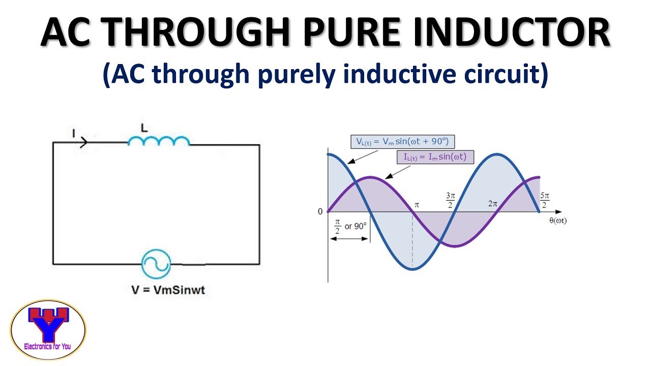
AC through pure Inductor | AC through purely inductive circuit - YouTube